Modbus Server
Starting in version 1.65, which was released in February of 2025, the PLC Shift runtime has a Modbus TCP server. This lets you read and write tags values using the Modbus protocol without having to map the tags to the PLC. This is different feature from the Modbus PLC feature, which allows you to read and write tags from a controller using the Modbus protocol.
Each application for a given device has its own configurable Modbus TCP Unit ID (also know as a station ID) and to keep things simple, addresses are automatically assigned to tags. Because each app has its own Unit ID, address contention between tags in different apps is not possible.
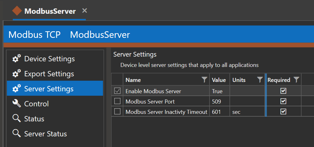
Device Level Settings
Modbus server settings at the device level are shown below. These settings apply to all applications. You can use these settings to enable or disable the Modbus server, set the port that the server listens on, as well as other settings. When the server is enabled, it will listen for incoming connections on the configured port on all adapters. Note that the device's firewall will need to be configured to let incoming connections through on the configured port.
The device's firewall must be configured manually to allow incoming connections to the Modbus server.
|
Device Level Settings
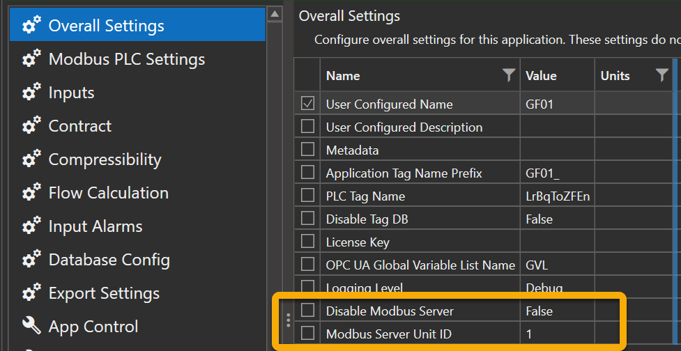
App Level Settings
Application level settings for the Modbus server are shown below. Each application, regardless of whether its disabled, must have a unique Unit ID if the Modbus server is enabled at the device level. If the Modbus server is not used, and not enabled at the device level, then the Unit ID setting doesn't matter.
The Unit ID is validated when an export file is generated and is not validated otherwise.
Unit IDs at the app level MUST be unique if the Modbus server is enabled.
|
Modbus Server App Level Settings
Address Assignment
Each parameter has a 'Modbus Server' checkbox in its detail view. When this option is checked, the parameter is automatically assigned an integer index which indicates the order in which the Modbus server option was enabled for this parameter. The first parameter that is selected has an index of 1, the next has an index of 2 and so on. When the 'Modbus Server' option on a parameter is unchecked, the index for that parameter is set to 0.
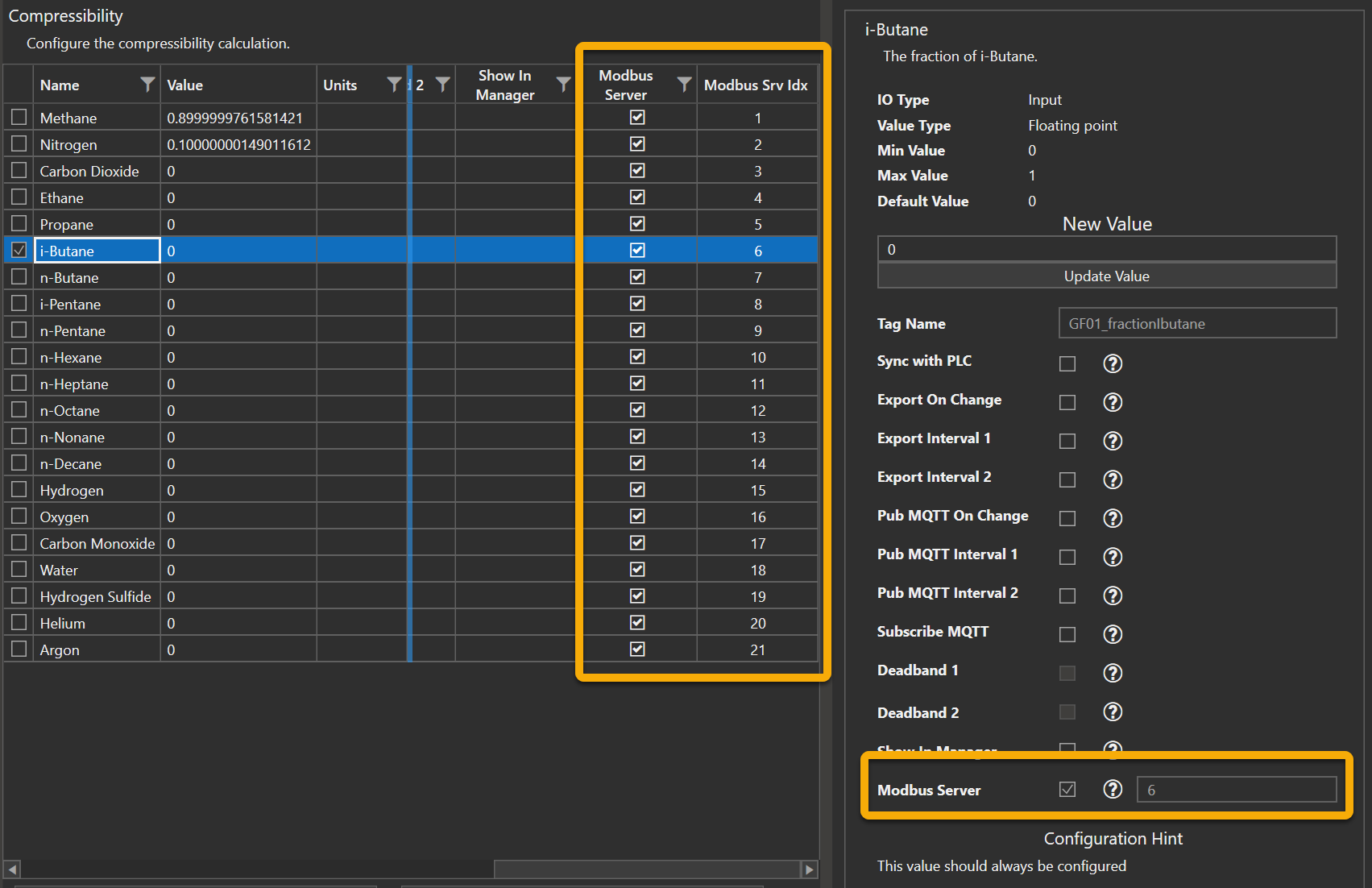
Modbus Server Address Assignment
The index is not a Modbus address. It simply indicates the order in which the parameter had its 'Modbus Server' option checked. A parameter will always be assigned the next value after the previously assigned index. For example, if we select three parameters, and they get assigned 1, 2, and 3, and then we deselect those parameters, which sets the index for all three parameters to 0, then the next parameter selected will be assigned an index of 4.
A parameter's Modbus server index is not an address but rather indicates the relative order in which Modbus registers will be assigned to the parameter's value.
|
At runtime, or when we generate the export, each selected parameter will automatically be assigned address(e)s based on the index and parameter value type. The parameter with the lowest index will be assigned the first register address(es), the parameter with the next index will be assigned the next address(es) and so on. A 32 bit value will be assigned two register addresses, a boolean value will be assigned to a contact or coil and so on.
The indexes are persistent across app restarts and are included in configuration exports and imports. This means once an index is assigned, the parameter's Modbus address will always be the same as long as no previously selected parameter is deselected. Newly selected parameters are added to the end of the list.
Addresses are always assigned starting at register 40001 for holding registers, 30001 for inputs, 10001 for contacts and 1 for coils.
Use features on the Compare tab to copy indexes from one app to another. This allows you to copy the Modbus map from one app to another, as long as the apps are the same type and at the same version.
The Modbus server indexes can be copied from one app to another using the Compare tab, resulting in identical Modbus maps for both apps.
|
Modbus Server Export
There are two options under the 'File -> Export -> Modbus Server' menu at the top of the main window. Do not select the 'Modbus PLC' option.
Take care to select the 'Modbus Server' option. Do not select the 'Modbus PLC' option.
|
CSV/XLSX
Select this option to generate a generic export in CSV or XLSX format. The exported file will list errors, if any exist, and will show the addresses that are assigned for each parameter than has its 'Modbus Server' option checked.
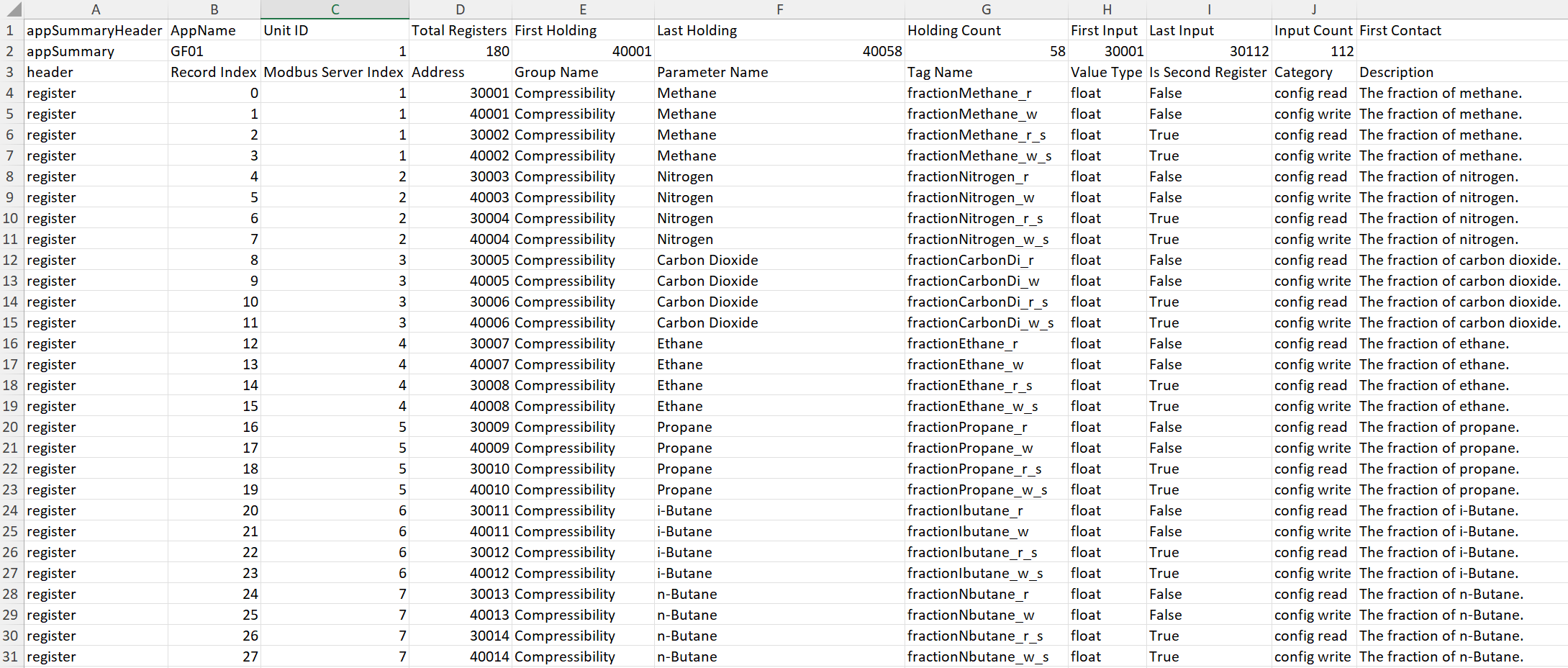
Modbus Server Export, XLSX Example
Inductive Automation Ignition
Select this option to generate a JSON formatted export that can be imported directly into Ignition.
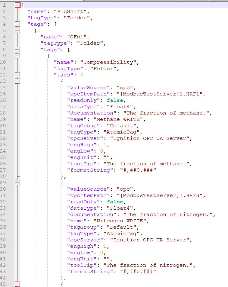
Modbus Server Export, Ignition JSON
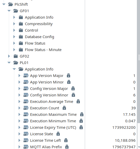
Modbus Tags in Ignition
Additional Information
Register Ordering
The Modbus protocol has no support for 32 bit values. 32 bit values are sent by combining two 16 bit registers, but there is no standard on which register should contain which bytes.
The PLC Shift Modbus server sends the least significant bytes of a 32 bit value in the first (lower numbered) register and the most significant bytes in the second (higher numbered) register. This is not configurable and applies to read and write requests.
For example, if a 32 bit value is stored in registers 40007 and 40008, register 40007 would contain the least significant bytes and register 40008 would contain the most significant bytes. This ordering applies to both 32 bit floating point and integer values.
Supported Function Codes
The PLC Shift Modbus server supports the function codes listed below. The server will respond to unsupported function codes with a Modbus exception message.
-
FC01, read multiple coils.
-
FC02, read multiple contacts.
-
FC03, read multiple holding registers.
-
FC04, read multiple input registers.
-
FC05, write single coil.
-
FC06, write single holding register.
-
FC15, write multiple coils.
-
FC16, write multiple holding registers.
Registers Out of Range
Read requests for registers that are not mapped to tags will result in the Modbus server returning zeroes to the client for the nonexistent registers. Writes to nonexistent registers will result in a success message to the client, but no tag values will be written.