Top Menu
The top menu at the top of the PLC Shift Manager window allows you to undertake the actions listed below. Some options, especially in the 'File' menu are context sensitive and depend on which item is highlighted in the tree view.
Take care to select the correct item in the tree view when trying to undertake a context sensitive action. Checking an item does not select it. To select an item, click on it and then immediately go to the Top menu.
|
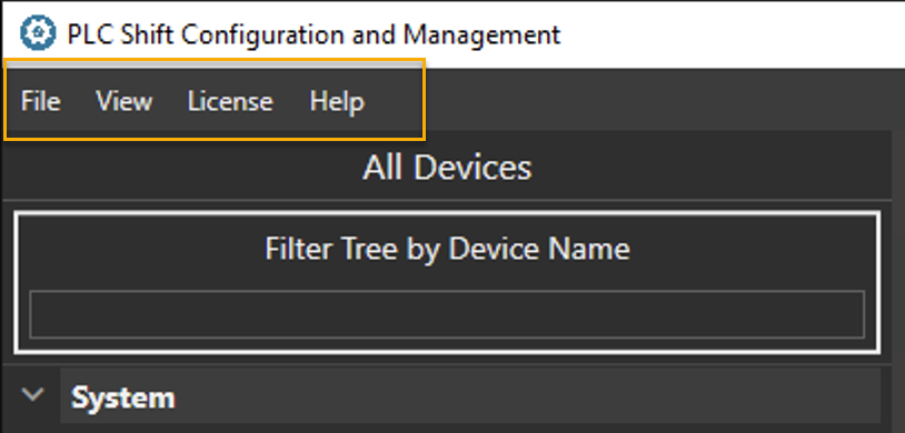
PLC Shift Manager - Top Menu
File
Preferences
Use the settings here to change global options, like the color theme.
Import
Configurations
Use this option to import device and application configurations that were previously exported.
Export
Export to File
Use this option to export device and application configurations to a file. The export depends on the selection in the tree view. To export just a single application configuration, select an application. To export a device and all of its applications, select a device. To export all devices and applications, select the 'System' node in the tree view.
Export all devices and applications periodically to make system backups.
|
L5X UDT
Use this option to export the selected device or application in the tree view as an Rockwell Logix UDT (user defined type). This will create a single file with multiple UDTs in it. Each application will have a UDT for each group that has at least one parameter that has its 'Sync with PLC' option checked. A top level for each application will be created that references the group UDTs. In this way, it's possible to create a single tag in Rockwell Studio 5000 that holds the structure for an entire app as a hierarchical model.
See the 'Logix EtherNET/IP' section for more details on how to use this export.
Modbus PLC
Use this option to generate an export of the selected device in the tree view. For each app in he export, the export file will contain a list of parameters that have the 'Sync with PLC' option checked. Modbus register addresses are assigned sequentially starting from the configured base addresses in the app's 'Modbus TCP Settings' group.
This option is only available when a device is selected in the tree view.
When multiple apps are selected, care must be taken to change the Modbus base addresses for each app from their default values to avoid register overlaps. Any overlaps appear as errors on the export file.
Ensure that there are no register overlaps when exporting multiple apps at once. The export file will flag any register overlaps
|
Careful selection of the register base addresses will minimize register gaps and allow for efficient polling at run time.
|
The export can be in either Microsoft Excel or CSV (comma separated values) format. To change the format, choose the appropriate file extension in the 'Save as Type' field in the file picker window.
See the Modbus PLC section for more details on how to use this export file.
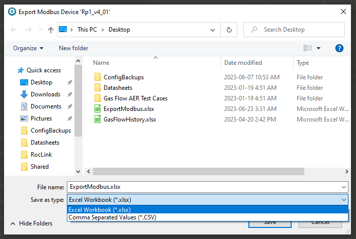
FIle Picker - Choose the Export File Type
Remote Connect
Use this option generate an export for Schneider Electric Remote Connect software that is used to manage SCADAPack RTUs. For each app in the export, the export files will contain a list of parameters that have the 'Sync with PLC' option checked.
The file that is generated cannot be imported into Remote Connect directly. First generate an export from Remote Connect and then copy and paste the contents of this file into that exported file and then import the updated file into Remote Connect. The columns in this export file align with the columns in the export file that is generated by Remote Connect.
See the SCADAPack 47xi section for more details on how to use this file.
CODESYS DUT
Use this option to generate an export file that can be imported into CODESYS as a DUT (data unit type) structure. or each app in the export, the export files will contain a list of parameters that have the 'Sync with PLC' option checked.
The file itself is just text. The contents of the file can be copied into a STRUCT DUT in CODESYS. See the 'CODESYS OPC-UA' section for more information on how to use this file
Sensia HCC2
Create a CSV file that has tag and Modbus register information for Sensia's HCC2 RTU. The export file will contain a list of parameters that have the 'Sync with PLC' option checked.
Modbus Server
Starting in version 1.65 (February 2025), the PLC Shift runtime has an integrated Modbus server. This feature allows you to read and write values using the Modbus protocol. See the Modbus Server section for more details.
Bulk Edit
Starting in version 2.08 (July 2025), you can export the complete configuration of an app to a MS Excel file (xlsx), make changes, and then import the file and apply the changes to an app. This allows advanced users to make change quickly and cut and paste configuration chunks from one section of an app to another.
Bulk Edit options were added under the Export and Import menus.
Take care when using the Bulk Edit features. Application configurations are over written and some options and values, especially those requiring cross validation, can be set to illegal values.
|
View
Use this option to show the Compare tab. Applications that are the same type and same configuration version can be compared to see the differences between their configuration. You can compare Plunger Lift at version1.3 against another Plunger Lift at version 1.3. but you cannot compare Plunger Lift at version 1.3 against any other version, or Plunger Lift against Gas Lift.
To use the compare tab, drag applications from the tree view to the 'First Application' and 'Second Application' spots on the compare tab, and then click the 'Show Differences' button.
If any differences exist, you can select the differences and then copy them from application 1 to application 2 or vice versa. Use the buttons in each column header of the grid view to filter for specific types of differences or parameters.
Starting in Version 1.65, which was released in February of 2025, the PLC Shift runtime has a Modbus server. This allows you to read and write tags in the app using the Modbus protocol without mapping the tags to the PLC. The Compare tab allows you to copy Modbus addresses from one app to another so that they have the same Modbus map. See the Modbus Server section for more details
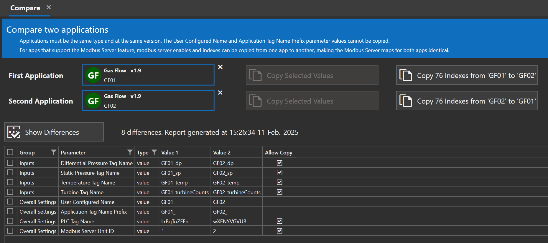
Compare Tab - Show Differences
Show SQL Folder
This option starts Windows Explorer and shows a directory that contains database configuration scripts. These scripts can be used to prepare a database with the right tables so that flow computer history can be exported directly to the database.
See the MS SQL Server and ClickHouse sections for more details.
TE BLE Sensors
This option opens a tab that lets you work with TE Connectivity BLE (Bluetooth Low Energy) wireless and battery operated sensors. Supported sensors include the M5601 pressure sensor family and the D5601 differential pressure family.
In the future the PLC Shift Gas Flow computer will be modified to work with these sensors. However, the app will not be able to configure the sensors. Configuration of the sensors, including the sensor name and update rate, must be done in PLC Shift Manager.
Configuration of the BLE sensors must be done using PLC Shift Manager and cannot be done at runtime in the Gas Flow app.
|
To communicate with the sensors, we use Ezurio BLE654 USB to Bluetooth dongle that is configured specifically for our application. Only part number 451-00003 can be used. No other Bluetooth dongle or radio is supported, including other BLE654 part numbers.
A BLE654 dongle appears as a virtual serial port on a Windows Computer. With a dongle connected, click the 'Open BLE Dongle' button. This opens the virtual comm port and configures the dongle, if required.
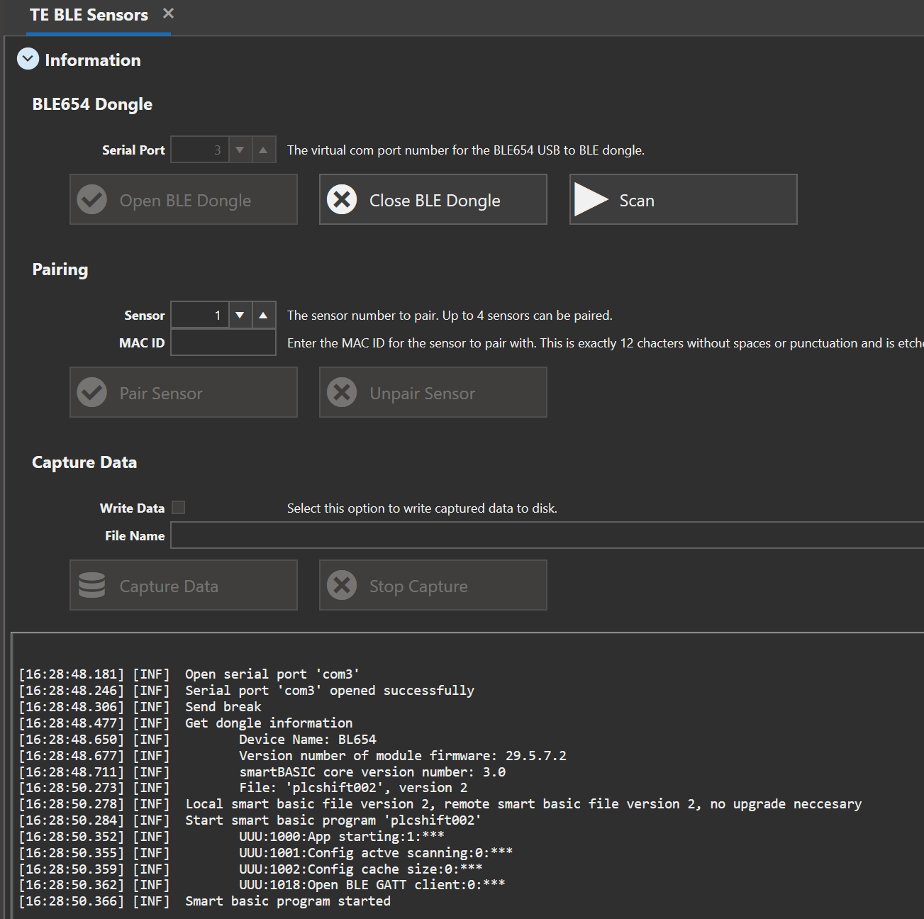
TE BLE Sensors Configuration
Once the dongle is configured, we can pair up to 4 sensors. To pair a sensor, we need the Bluetooth MAC ID, which can be read off the sensor itself. The MAC ID is exactly 12 hexadecimal characters without any spaces or punctuation.
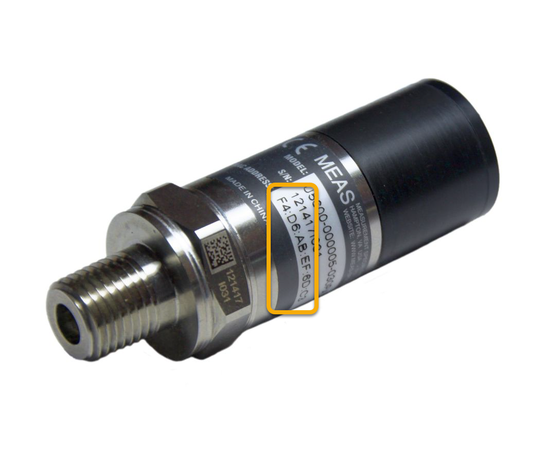
Bluetooth MAC ID on Sensor
TE Connectivity BLE sensors come in two different variants. One variant allows pairing at any time (pairing mode), while the other type only allows pairing within the first 6 hours after power is applied (beaconing mode). The PLC Shift Gas Flow application can only work with pairing mode sensors. This document has additional details.
The PLC Shift Gas Flow application can only work with sensors that support pairing mode.
|
Beaconing mode sensors can be used for testing with PLC Shift Manager, but since they can only be paired within 6 hours of power being applied, they are not useful for an unmonitored application
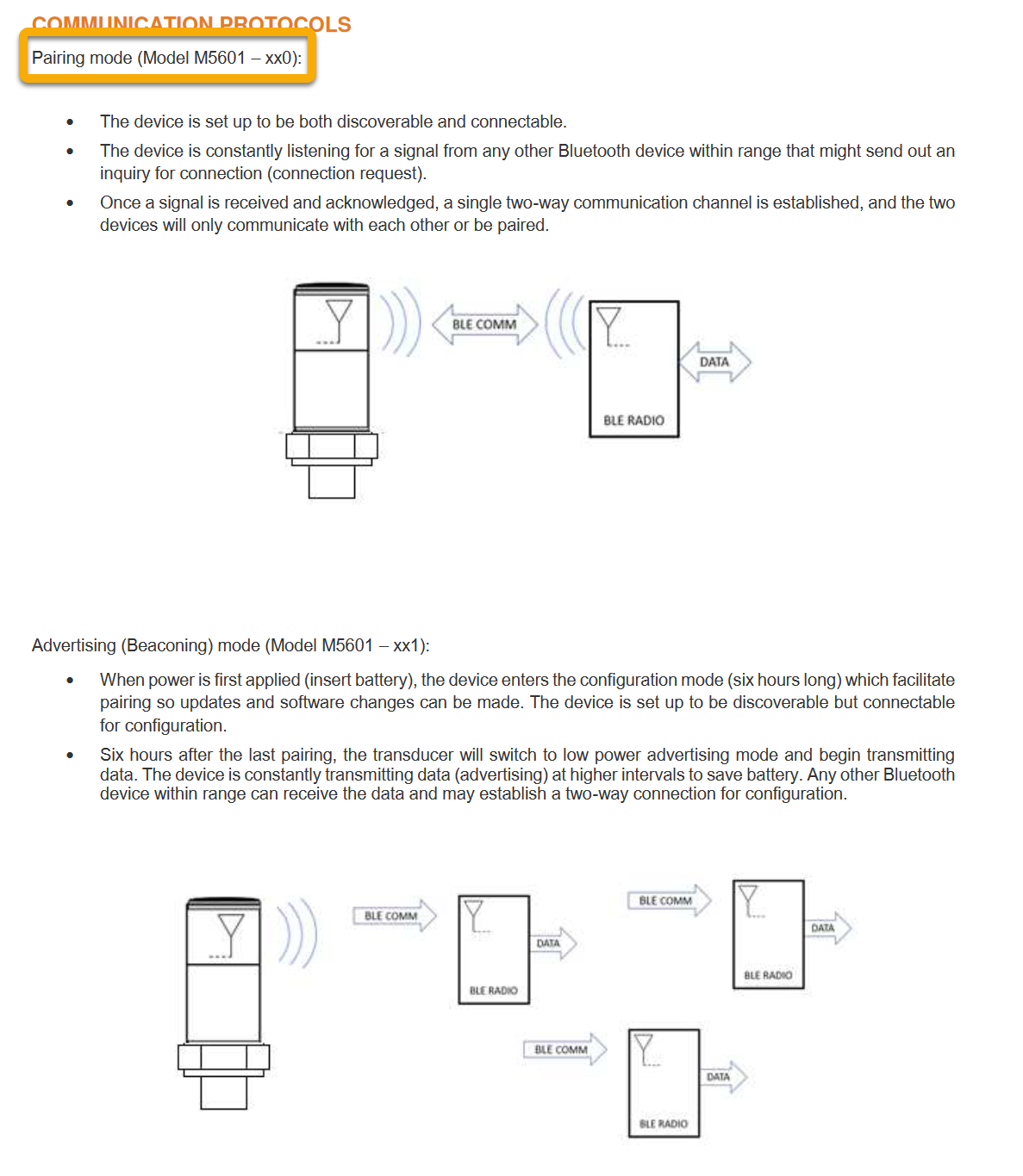
Pairing mode vs Beaconing Mode
Once a sensor a paired, view the tab for that sensor and change the update rate and device name if desired.
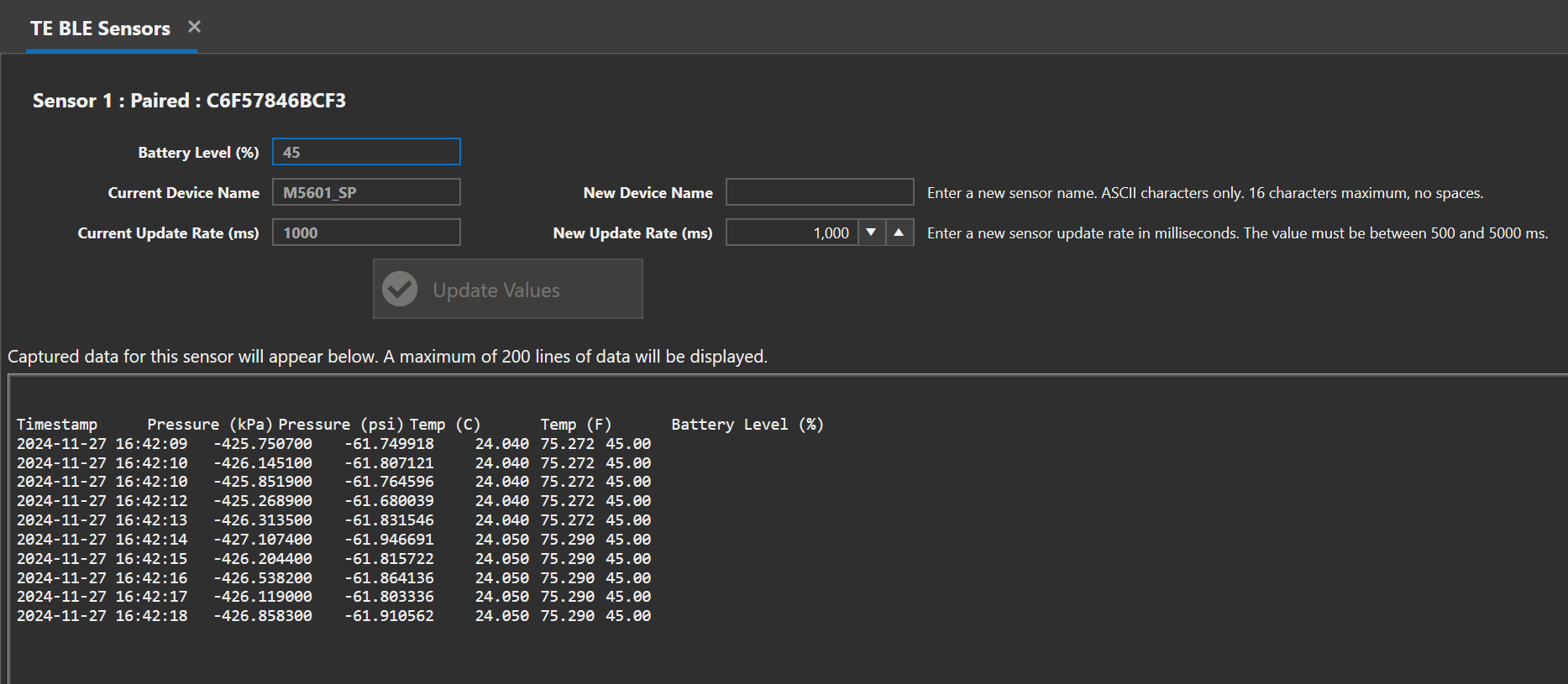
Configure Sensor and Capture Data
Once the sensors are configured correctly, Click the 'Capture Data' button to read data from the sensors. Data will appear in the tab for each sensor, and data can also be written to disk in CSV. Data is pushed from the sensor, and as such, data will appear at whatever the configured update rate for each sensor is.
The battery voltage is shown alongside the sensor data, however, since the battery voltage changes slowly, it's actually only read from the sensor once per minute.
License
See the 'Licensing' section for more details. Use the 'License Request' option to generate a license request. Use the 'Decode License' option to decode a license file and view its contents.
Help
This menu contains options to let you view information about PLC Shift Manager.
About
Get the current version and build date and time for PLC Shift Manager.
Help
View this manual.
Release Notes
See what's changed with every version that is released.
Eula
View the End User License Agreement (EULA). You must agree to this before PLC Shift Manager starts.
Attributions
PLC Shift uses open source code and libraries. These are listed in this section.
