
Well Test - Codesys
For this demo, the automation piece is a Codesys project. The project has a single task which runs at 200 ms with three structured text programs in that task. The entire project is available for download from the Well Test - Downloads section. The project sections are described in detail below.
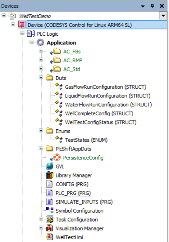
Codesys Project Tree View
DUTS
This folder contains structures (types) that define the configuration of a well to test. There is a structure for each run type (gas, liquid, water), and then an overall structure that includes one of each of these run-specific structures as well as overall information about the well to test.
Enums
This folder contains a single 'TestStates' enumeration that describes the states for the main state machine. The code that uses this enumeration is in the 'PLC_PRG' file.
PLC Shift App DUTs
The PlcShiftAppDuts folder contains the DUTs that were exported from PLC Shift Manager. Each flow run has its own DUT. At runtime, the apps read and write these tags, which is how we link PLC Shift apps to a Codesys Soft PLC. See the Codesys OPC UA section for more details on how this works.
GVL
This is where we create global variables that are accessible to PLC Shift apps via OPC UA. For this demo project, this file is a mix of tags that will be accessed by PLC Shift apps, and other tags that are global in scope.
Well configurations are stored in the 'WellConfigurations' array. When a well is put on test, we grab the well configuration from this array using the index of the well that is being tested. Adding more storage for well configurations is as easy as expanding the size of this array. We've created an array that can hold 10 well configurations, but we actually only use 5 of them. See the PLC_PRG program for more details on how well configurations are stored and loaded.
Symbol Configuration
This section is used to make variables from the program available externally. Make sure that the app tags appear here so that the PLC Shift runtime can access the tags via OPC UA. Build this manually using the 'Build' button when any DUT that appears here is changed.
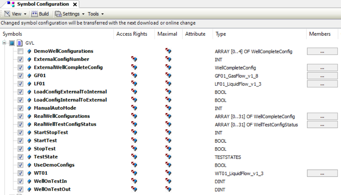
Codesys Symbol Configuration
Simulate Inputs Program
To make the demo portable, and avoid a dependency on real IO or sensors, the SIMULATE_INPUTS program is used to generate inputs to the flow computers. This program executes under the Main Task at a rate of 200ms.
The code increases each variable by the seconds today multiplied by some factor. It also uses the system clock to generate some noise so that values aren't a straight ramp. Once values are generated, they are written to the flow computers' input tags.
Config Program
This program takes well test configurations from externally accessible tags and stores them in the internal configuration array, or it can push configurations from the internal well test array out to external tags.
Main Program
The PLC_PRG program is the main program for this demo. This is where we actually control the well test. This program has a few different sections, which are explained at a high level below. This program executes under the Main Task at a rate of 200ms.
Well Configurations
At the bottom of PLC_PRG there is a large chunk of code that defines configurations for 5 different wells. These are populated into the 'GVL.WellConfigurations' variable when the 'LoadConfigurations' variable is set. Note that the configuration for well 3, at index 2, has an invalid gas composition. The sum of the hexanes+ components is out of range for AGA 8 1994. This is used to show what happens when the configuration of a flow run fails validation.
To use these hard coded configuration, set the 'GVL.UseDemoConfigs' tag to 'TRUE'. Set 'GVL.UseDemoConfigs' tag to 'FALSE' to use the 'GVL.RealWellConfigurations' array. Configurations must be loaded into the real array before it can be used. The real configurations use Codesys' Persistence Manager feature to save configurations to disk and to load configurations from disk when the app is started.
The demo configuration for well 3, at index 2, is purposefully invalid.
|
When not using the demo configurations, the 'GVL.RealWellConfigurations' array must be loaded before well testing is possible.
|
When a well test is started, we take the well on test variable from the HMI, which ranges from 1 to 5, subtract 1, to get a number from 0 to 4, and then use that number as an index for the 'GVL.DemoWellConfigurations' array to retrieve the configuration for the well on test.
Adding more wells can be done by increasing the size of the 'GVL.RealWellConfigurations' array. This is configured to hold 32 well configurations.
Main State Machine
The bulk of the work for the program is done in the main state machine. This is a large IF THEN ELSE structure that moves between the various states as defined in the 'TestStates' enumeration. The code and the state transitions are well documented, so we won't get into the details here.
Additional Code
Outside of the main state machine, there are various small chunks of helper code.
-
Start/Stop. This code converts the start and stop radio buttons from the HMI from an integer into boolean values.
-
HMI State. This code converts the internal state into a string that can be displayed on the HMI. Not all internal states are mapped because the program moves through some of those internal states very quickly.
-
Connection State. This code checks that the applications execution counts are always changing. When the counts are changing we can be sure that PLC Shift apps are working and connected to the PLC.
-
Convert Timestamps. This code converts timestamps from the flow computer, which are in unix seconds, into DATE_AND_TIME values which can be displayed in the HMI.
-
Alarms Active. This code determines whether any flow computer alarms and active and if alarms are active, the HMI is updated.